Case Study 2: Pump Activation
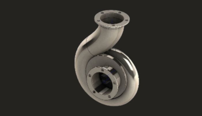
In this case study, we demonstrate our capabilities in conducting detailed centrifugal pump cavitation analysis. Our team was tasked with evaluating the operating regimes of a centrifugal pump to identify areas prone to cavitation.
By applying advanced CFD modelling techniques, we analysed the pump’s performance under various conditions, optimised its geometry, and provided solutions to improve efficiency and reduce cavitation risks.
The insights gained from this project were crucial in enhancing the pump’s overall performance and durability.
The requirement
XYZ Company acquired our services to provide them with the Centrifugal Pump Cavitation Analysis. The case study for this project is as follows:
The requirement of the company was to study the regimes at which a given centrifugal pump was experiencing cavitation. The pump operating regime was 1200 RPM. The inlet pressure was 1.9 Bar.
The customer demanded to identify a set of geometrical parameters to be optimised thereby improving the pump tendency to suffer cavitation.
A double phase fluid was set up with Water/Water Vapour phases to study the phase changes. The company needed Wide Design to provide the pump efficiency curve amongst pressure fields data at different regimes and to this end supplied the boundary operating conditions of the pump.
The customer demanded suitable improvements to be investigated to improve the tendency of the pump to incur cavitation.
The Process
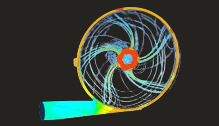
Wide design started out with a working plan. We generated a simple but effective rotating domain with inflated mesh boundary layers on all the outer surfaces. The Inlet and outlet had both pressure conditions set.
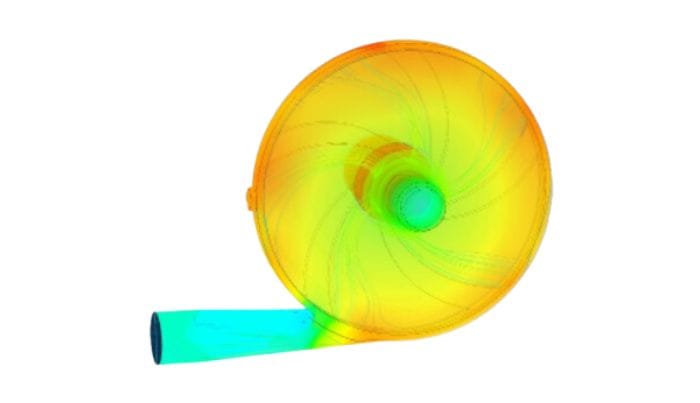
A baseline simple analysis was carried out that helped confirm the solidity of the boundary conditions chosen. Three different rotation regimes were studied that helped corroborate the real device measured output flow rate with the calculated flow rate achieved. The flow rate results in the three pressure conditions displayed a 5%, 7% and 4% error when compared with the real device at corresponding pressure rates.
This conclusion pointed at some potential development in the model physics but the output conditions were in real life variable and at this stage it was considered more effective to use the working CFD model to investigate cavitations likelihood.
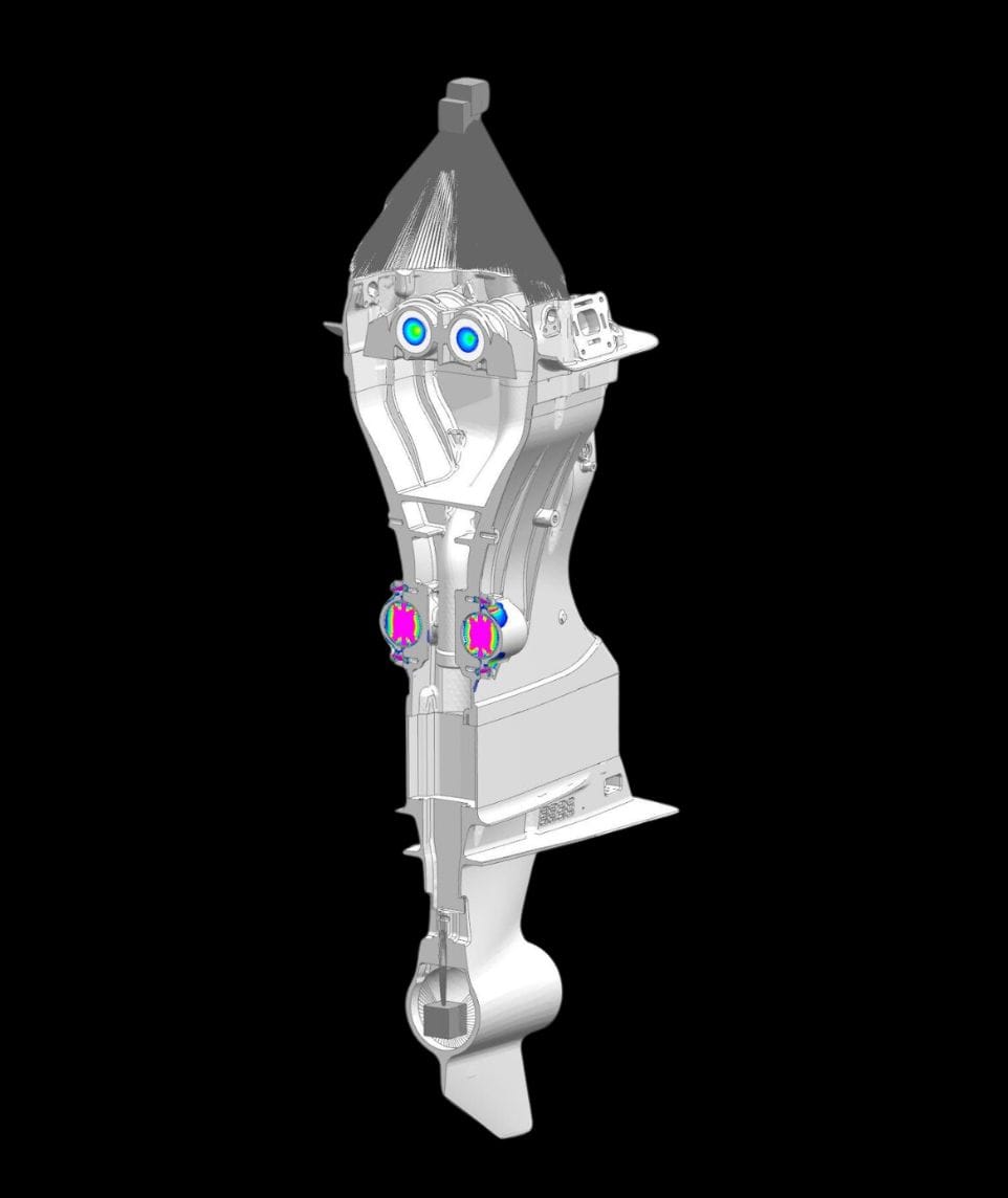
The CFD model as constrained by WD pointed at some clear localized negative pressure field formation around the root of the rotor blades. Even with all the assumptions made these results was sufficient to conclude that some geometry modifications were needed to avoid the spot erosion witnessed in the rotor. This was present in smaller and larger forms in all of the three different pressure fields.
A transient analysis was further curried out for each of the three rotating regimes where the range of speed was varied between 10% lower and 10% higher than the nominal three rotating speed selected. The first two sets of speeds revealed a lot more information as to how the flow was developing inside the flow domain and where the pressure fields were developing differently.
At the highest speed this type of range analysis helped identify a pressure stall formation zone which developed at the rotor blade root. In this location vortexes were forming and the flow phase change was not very clear. These proved to be very important results to understand the flow field in the rotating domain and it helped making significant steps in the geometry development of the pump.
The initial baseline physics set up proved essential to help reiterate the CFD analysis with the same physics in a smart and efficient way.
The outcome
Building upon the results of our initial analysis, we identified several key design improvements to optimise the pump’s performance.
We worked closely with the client to implement these changes, assisting in the construction and testing of the pump’s enhanced prototype. Throughout this phase, we gathered critical performance data to guide the next steps in our CFD analysis.
Our efforts established a strong correlation between the simulated results and real-world performance, particularly in terms of pressure fields, flow rate, and the pump’s torque and power output, which were within 3% of the actual measured values.
This high level of accuracy not only validated our approach but also highlighted our commitment to delivering reliable, data-driven solutions.
By refining the pump’s design, we improved its efficiency and durability, showcasing our expertise in creating practical, high-performance engineering solutions.